


The Locking Coupling: A key factor for hole deviation control
The Locking Coupling: A key factor for hole deviation control
For our regular ‘Field practice’ feature, we ask coring experts to write a brief summary of their particular area of expertise. Here, Laurie Cyr and Grigor Topev combine efforts to tell us all we need to know about locking couplings and how to choose the right type.
Locking coupling function
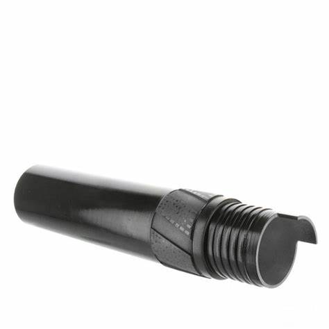
The locking coupling (LC) is a part of the well-known Boart Longyear’s Genuine Q™ wireline system. It is the uppermost part of the core barrel outer tube that connects with the drill rods. The main functions of the LC are:
To provide an inner shoulder where the latches of the inner tube head assembly can lock onto
To provide an adaptor between the core barrel outer tube and the drill rods
By means of a tang, to stop the head assembly rotating inside the LC, preventing the latches from premature wear
To provide varying degrees of stabilization in order to minimize deviation while drilling
The first three functions can be classified as technical, while the fourth and most important one is more technological, being related to borehole deviation control.
Locking coupling types
Locking couplings can be categorised according to the amount of stabilization they provide.
Blank locking couplings
Blank locking couplings
Black, standard and full hole locking couplings
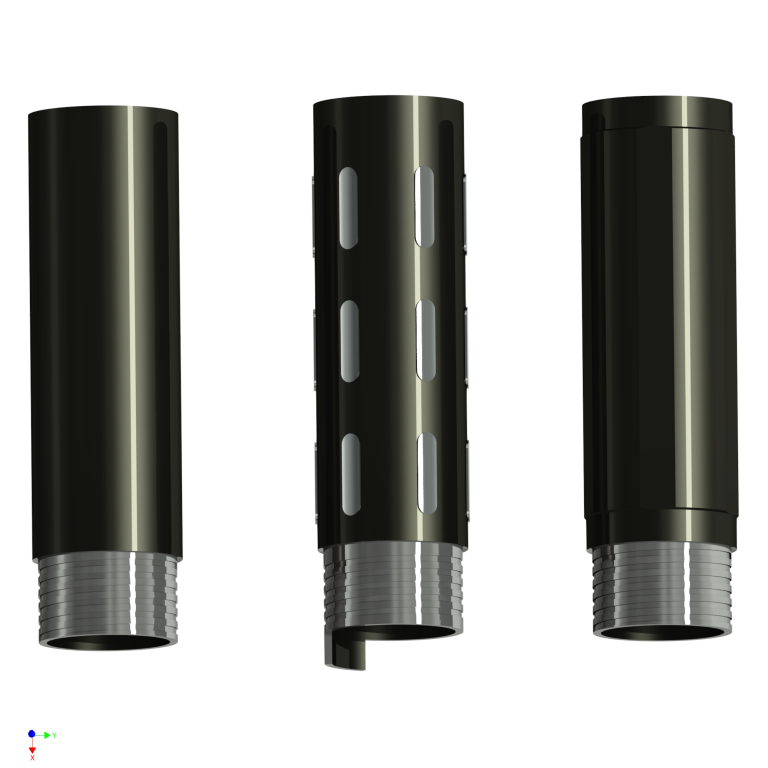
Blank locking couplings have the same diameter (73.00mm) as the standard core barrel, without additional tungsten carbide pads or hard welding. Blank locking couplings are the cheapest type, but are only suitable for short holes where natural deviation will not be significant. Rarely used nowadays.
Standard couplings
Standard couplings are equipped with hard tungsten carbide pads to provide a degree of stabilization. Hard welding can also be used instead of pads. The standard coupling is full hole size. When deviation occurs, the pads tend to wear out quickly, resulting in even greater deviation. This type is best used in areas with little potential deviation, and is well established and commonly used.
Hex, or full hole locking couplings
These have six sections around their girth with an outer diameter of 75.00mm. “Full hole” is actually a misnomer. The hex LC provides good stability compared to the blank LC, and almost as much as the standard coupling. The hex LC is not wear-resistant and stabilization can quickly deteriorate. A common error with this type of LC is that it is often replaced only when the sections have become totally flat, a mistake where hole deviation control is a key factor. Due to its over-gauge size, any full-hole element of the outer tube is more liable to get stuck in certain geological conditions. The hex is a common and widely used type of LC.
Diamond locking couplings, also called back-end reamer
Diamond locking couplings, also called back-end reamer
One or more solid rings of diamonds baked onto the locking coupling, like the standard reaming shell. This unit is wear-resistant and will last longer than the other types. It provides real hole stabilization, but it should be borne in mind that the diamonds-embedded sections are cutting elements and in rare cases might actually increase hole deviation. Water flow is more restricted as compared with other coupling, especially if the adaptor coupling, outer tube and reaming shell are also full hole type. Care should be taken in loose ground, as it is very easy to get this equipment stuck in the hole.
Lately, a variation of this type of coupling has become popular: a diamond LC with full hole body, usually with spiral water channels. The diamond sections protect the full hole body from wear, and the full hole body minimises the sideways cutting tendency of the diamond sections mentioned above. The full hole diamond coupling offers the optimum combination for hole stabilisation where ground conditions permit. This is the most expensive coupling.
Common issues
The tang
The tang prevents the inner tube head assembly from rotating inside the LC, thus avoiding wear both on them and on the inner surface of the adaptor coupling. With the help of a thrust bearing, the inner tube will theoretically remain stationary as the core enters it, even when the rest of the core barrel, including the head assembly, is rotating.
Problems arise when thrust bearings malfunction. That failure often occurs when drilling continues after core-block in the inner tube or when the bearing is not lubricated regularly. Bearing failure will cause the latches to dig into the tang and damage it. Repeated instances cut a groove in the tang, allowing the latches to walk over it and eventually unlatch, resulting in rod pull.
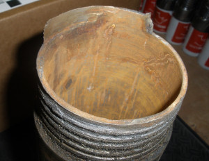
Stuck inner tube
Drill bits are often subject to several tons of pressure while drilling, and if core block occurs, all that weight is transmitted to the contact surface between the top of the latches and LC thread shoulder. That contact area is very small and narrow and is not designed to withstand such weight. This scenario usually results in a stuck inner tube, and most likely, rod pull. Often, attempts to release the inner tube with the overshot result in the wireline getting broken, compounding the problem. That is one reason drilling over core block should not be acceptable practice.
Although at first glance locking couplings are simple elements, their function in the wireline system is very important. The correct choice and use of locking couplings requires knowledge and experience, but only on-site testing will show what works best in specific conditions.
It should also be noted that the LC is only one of factors in deviation control and the authors of this article have listed only the main types and problems associated with the locking couplings.
| BQ NQ HQ PQ Nonimal Weight | kg | Ibs |
| BQ Locking Coupling(approx.) | 1.6 | 3.53 |
| NQ Locking Coupling(approx.) | 2.9 | 6.39 |
| HQ Locking Coupling(approx.) | 4.4 | 9.7 |
| PQ Locking Coupling(approx.) | 5.2 | 11.46 |
